GPUs for Deep Learning 🚀
This lecture synthesizes key insights on GPUs, focusing on their architecture, performance bottlenecks, and advanced optimization techniques crucial for scaling large language models (LLMs).
- 🔥 Core Message: While GPU computational power (especially for matrix multiplications) has scaled exponentially, memory access speed has not kept pace, making memory the primary bottleneck.
- 🧠 Key to Performance: Effective GPU utilization hinges on minimizing slow global memory access and maximizing the use of fast on-chip memory.
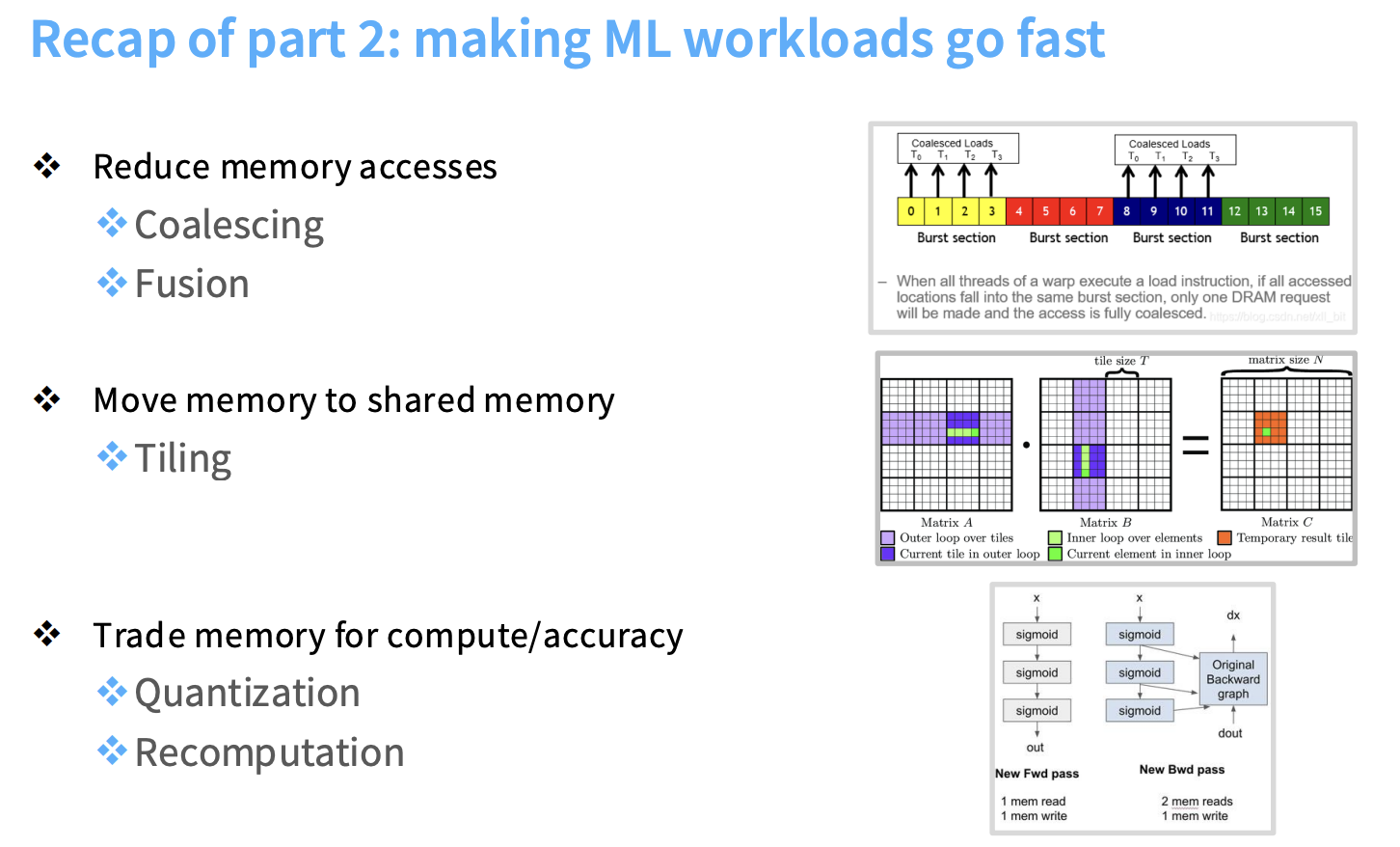
- 🛠️ Essential Techniques: Low-precision computation, operator fusion, recomputation, memory coalescing, and especially tiling, are essential for achieving high performance.
- ✨ Case Study: FlashAttention: These principles are exemplified by the architecture of FlashAttention, which dramatically accelerates the attention mechanism by cleverly applying these memory-aware optimizations.
1. GPU Architecture: Optimizing for Throughput
1.1. CPU vs. GPU Fundamental Differences
The fundamental distinction between CPUs and GPUs lies in their design goals:
- 🐢 CPUs (Central Processing Units): Optimize for latency, aiming to complete a few tasks as quickly as possible. They feature large control units, robust branching support, and large caches, but fewer processing cores.
- 🐇 GPUs (Graphics Processing Units): Optimize for throughput, aiming to process a large volume of data in parallel. They possess “many tiny compute units (ALUs)” and are designed for “many many threads,” making them ideal for parallelizable workloads like deep learning.
1.2. GPU Anatomy and Execution Model
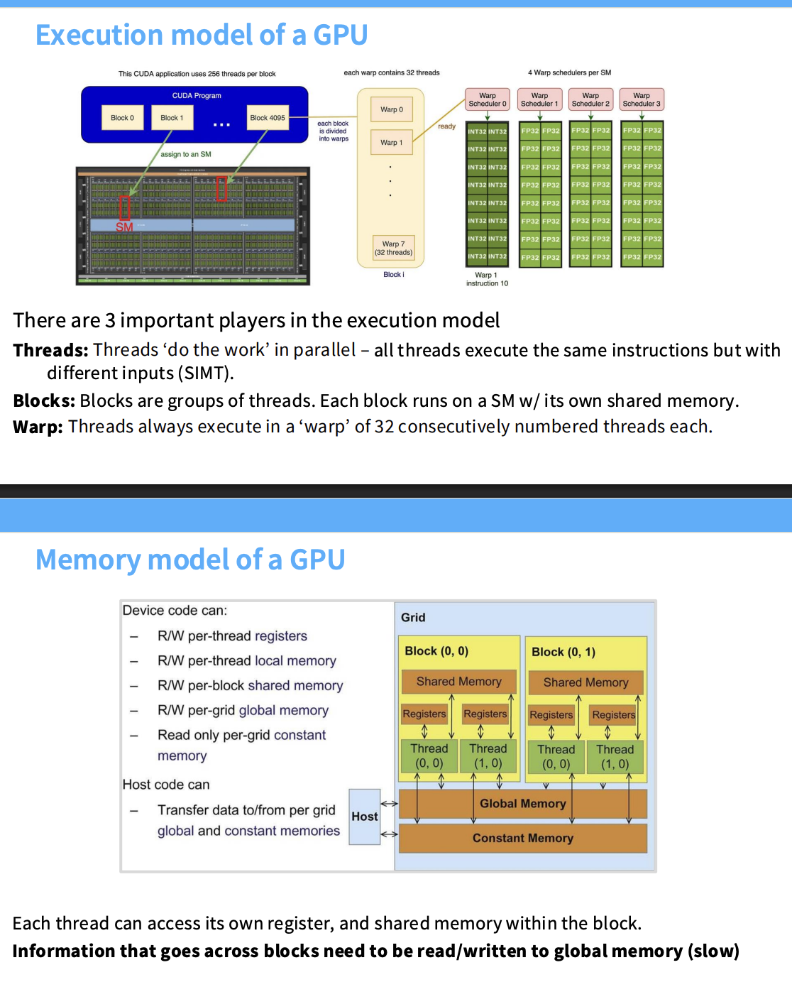
- Streaming Multiprocessors (SMs): GPUs contain numerous SMs, which act as independent processing units capable of executing “blocks” (jobs). An A100 GPU has 108 SMs.
- Streaming Processors (SPs): Each SM contains many SPs, which execute “threads” in parallel.
- Threads, Blocks, and Warps:
- Threads: Individual units of work, executing “the same instructions but with different inputs (SIMT).”
- Blocks: Groups of threads assigned to an SM, with their own shared memory.
- Warps: Threads execute in groups of 32. This Single Instruction, Multiple Thread (SIMT) model means all threads in a warp execute the same instruction.
1.3. GPU Memory Hierarchy
Memory proximity to the SM dictates speed:
- 🥇 Registers, L1 Cache, Shared Memory: The fastest, located inside the SM. Shared memory is crucial for data reuse within a block.
- 🥈 L2 Cache: On-die, but outside the SM, offering reasonable speed (approx. 10x slower than L1/shared memory).
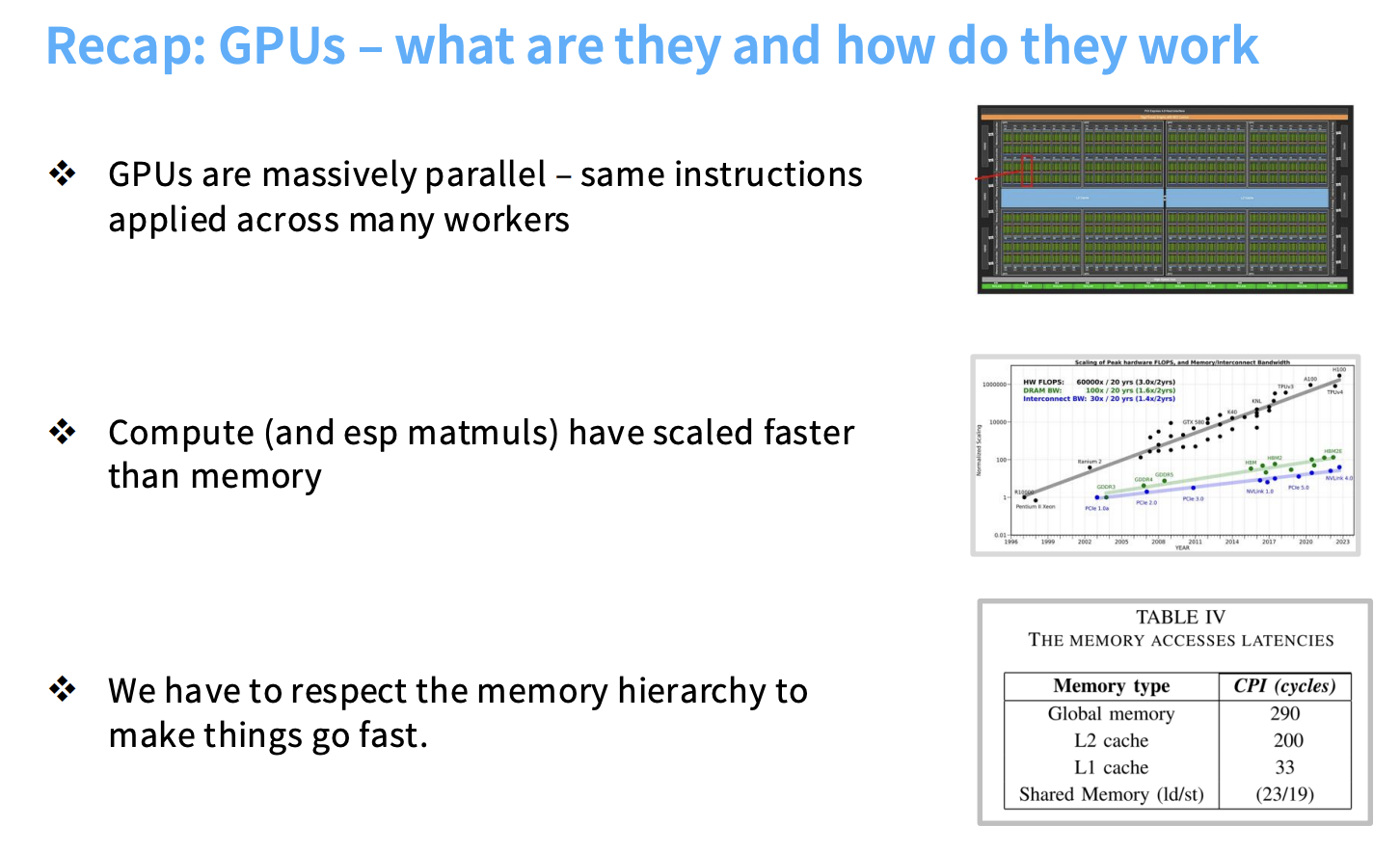
- 🥉 Global Memory (DRAM/HBM): The slowest memory, located off-chip. Accessing global memory is significantly slower (200-300 clock cycles vs. 20 for on-SM memory).
“Information that goes across blocks need to be read/written to global memory (slow).”
1.4. GPUs as Fast Matrix Multipliers
- Programmable Shaders: Early GPUs were leveraged for matrix multiplications through programmable shaders.
- Tensor Cores: Modern GPUs include specialized “Tensor cores… specialized matrix multiplication circuits.”
“Matmuls are >10x faster than other floating point ops!” This specialization is why “if you’re going to design any sort of a neural architecture… you have to have most of your workload be matrix multiplies.”
1.5. Compute vs. Memory Scaling
A critical observation is that “FLOPs scale faster than memory – it’s hard to keep our compute units fed with data!”
- Compute capabilities have scaled at an “astoundingly fast” rate.
- Memory bandwidth has grown much slower. This widening gap means “your bottlenecks are probably going to end up being memory.” Therefore, optimizing memory movement is paramount for high performance.
1.6. TPUs: Similar Principles
TPUs (Tensor Processing Units) share many conceptual similarities with GPUs, featuring “lightweight control, fast (big) matmul unit, fast memory.”
2. Understanding GPU Performance Bottlenecks and Optimization
GPU performance can be complex, often characterized by the “roofline model,” which distinguishes between memory-bound and compute-bound regimes. The goal is to avoid being memory-bound.
Key optimization tricks:
- Control divergence
- Low precision computation
- Operator fusion
- Recomputation
- Coalescing memory
- Tiling
2.1. Avoiding Memory Bottlenecks: Key Tricks
2.1.1 Control Divergence (Non-Memory Issue)
In the SIMT model, all threads in a warp execute the same instruction. Conditional statements can cause “significant overhead” because threads that do not meet the condition are paused, forcing serialized execution.
“Conditional statements within a single warp… can be really really damaging.”
2.1.2 Low Precision Computation (Quantization)
Using fewer bits (e.g., FP16 instead of FP32) “improves arithmetic intensity” by reducing the amount of data moved per operation.
2.1.3 Operator Fusion
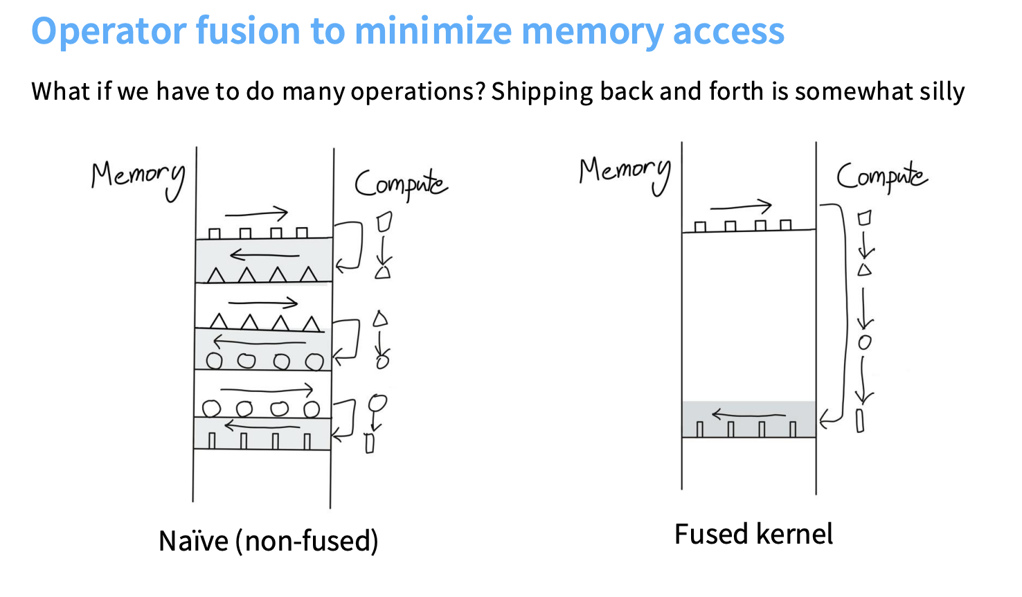 Operator fusion is a technique to make ML workloads faster on a GPU by minimizing access to slow global memory.
Think of a GPU like a factory:
- 🏭 Factory: The compute units.
- 📦 Warehouse: The memory from which inputs are drawn.
- 🚚 Conveyor Belts: The finite bandwidth for transferring data.
The core issue is the memory bottleneck: compute capabilities scale faster than memory bandwidth.
Problem with Naive (Non-Fused) Computation:
- Data is repeatedly moved back and forth between the “warehouse” (memory) and the “factory” (compute unit).
- This constant “shipping back and forth” incurs significant memory overhead and leaves compute units idling.
Solution with Fused Kernels:
- A “fused kernel” keeps data within faster, on-chip memory (shared memory or registers) for as long as possible.
- It performs all dependent operations on a piece of data sequentially before writing the final result back to global memory.
- This dramatically reduces memory round trips.
Example: sin^2(x) + cos^2(x)
- Naive Approach: Would launch five separate CUDA kernels, with lots of “back and forth” data movement for intermediate results (
sin(x),cos(x), etc.). - Fused Approach: All five operations are fused into a single kernel call. Intermediate results stay in fast on-chip memory.
Automatic Fusion:
- Compilers like
torch.compilecan perform many fusions automatically. Using such tools is strongly encouraged!
2.1.4 Recomputation (Memory-Compute Trade-off)
“Throwing away computation can actually be optimal.” Instead of storing intermediate activations (which is memory-intensive), one can recompute them on the fly. This “trades compute which you have too much of for memory bandwidth which you had too little of.” This is the same principle as gradient checkpointing.
2.1.5 Coalescing Memory Accesses
Coalescing is a global-memory access concept. In CUDA terms, global memory is the large address space that all blocks can address; on a typical NVIDIA GPU, its backing store is off-chip HBM, which is a kind of DRAM. It is large but expensive to access.
Do not confuse that with on-chip SRAM:
| Memory | What it is | Scope |
|---|---|---|
| HBM / global memory | Large, off-chip GPU DRAM | All blocks can address it |
| L2 cache | Hardware-managed on-chip SRAM cache | Shared across the GPU |
| L1 cache | Hardware-managed on-chip SRAM cache | Near one SM |
| Shared memory | Programmer-managed on-chip SRAM | Threads in one block |
| Registers | Fastest on-chip storage | One thread |
A global-memory load can be satisfied from L1 or L2 when data is cached, but the access pattern is still a global-memory pattern. Shared memory has a different concern—bank conflicts—rather than coalescing.
NVIDIA executes threads in a warp of 32 threads. At one global-memory load instruction, those 32 threads (also called lanes) present their addresses together. The hardware can combine nearby addresses into a small number of memory transactions:
Good: contiguous floats in one warp

T0 → x[0]    T1 → x[1]    ...    T31 → x[31]
For float, each thread requests 4 bytes. The warp therefore collectively covers a nearby 128-byte span. On modern NVIDIA GPUs that span is generally serviced using several adjacent 32-byte sectors; the useful mental model is simply “few transactions for one nearby span.”
Bad: scattered floats in one warp

T0 → x[0]    T1 → x[1024]    ...    T31 → x[31744]
The bad pattern touches many separate memory regions, so it needs many more transactions and wastes bandwidth. Coalescing does not mean all threads read the same float. The usual ideal is that they read different, adjacent values. Reading the same address can be efficient through broadcast/cache behavior, but it is not the main coalescing pattern.
For a simple vector-add kernel, consecutive thread indices naturally create a coalesced pattern:
int i = blockIdx.x * blockDim.x + threadIdx.x;
if (i < n) y[i] = x[i];
Within a warp, this commonly becomes x[0..31], then x[32..63], then x[64..95] in element indices. Since each float is 4 bytes, those are byte spans 0..127, 128..255, and 256..383.
“Memory accesses are coalesced if all the threads (in a warp) fall within the same burst.”
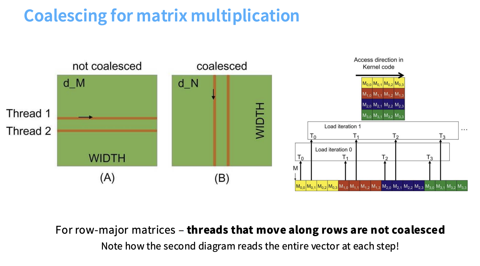
The matrix diagram below is easier to read if we focus on the warp at one load iteration, rather than the path followed by an individual thread over time. The four threads shown are a simplified warp.
For a row-major matrix:
M[row, col] = M[row * WIDTH + col]
The left, not coalesced, arrangement assigns neighboring threads to different rows. At iteration k:
T0 → M[0, k]
T1 → M[1, k]
T2 → M[2, k]
T3 → M[3, k]
Those addresses are separated by WIDTH in row-major storage. Each lane may walk left-to-right across its own row over time, but the lanes access far-apart locations at the same instant.
The right, coalesced, arrangement assigns neighboring threads to neighboring columns. At iteration k:
T0 → M[k, 0]
T1 → M[k, 1]
T2 → M[k, 2]
T3 → M[k, 3]
Those values are adjacent in a row-major array. The next iteration reads M[k + 1, 0..3]. Thus, each individual thread moves down a fixed column over time, but at every individual load instruction the threads collectively read a contiguous row slice. That is why the diagram says the second arrangement reads the entire vector at each step.
Coalescing makes each trip to HBM efficient. Tiling, discussed next, solves the complementary problem: it loads data into shared memory once and reuses it many times before another HBM trip is needed.
2.1.6 Tiling (The Big One)
Tiling is the practice of “grouping and ordering threads to minimize global memory access.” It’s a crucial technique to overcome the memory bottleneck.
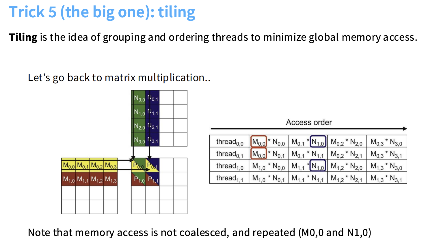
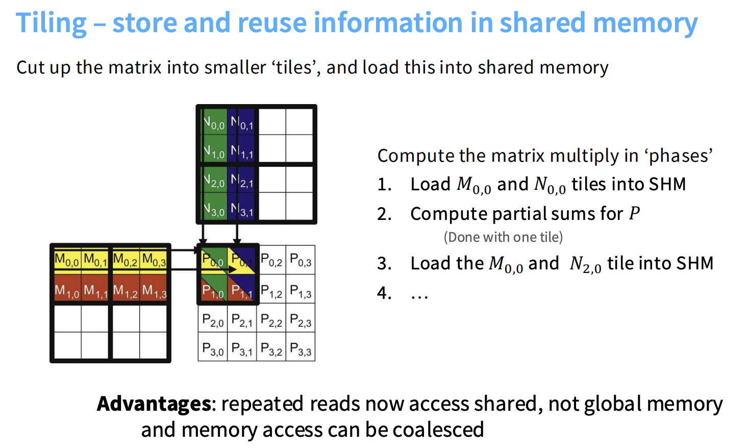
The Core Idea of Tiling:
- Break down a large computation (like a matrix multiplication) into smaller, manageable “tiles.”
- Load one current pair of input tiles into the block’s fast shared memory.
- Perform a significant amount of computation on the tile data before writing the final results back to slow global memory.
Tiling for Matrix Multiplication: A Worked Example
The full A and B matrices begin in HBM/global memory. A thread block owns a small output tile of C; it does not copy all of A and B into shared memory. Shared memory is far too small. Instead, the block repeatedly loads one current A/B pair along the inner K dimension, uses that pair completely, and overwrites it with the next pair.
For a deliberately tiny example, let a block of four threads compute a 2×2 tile of C from a 2×4 A and a 4×2 B:
A =                         B =

[a00 a01 | a02 a03]         [b00 b01]
[a10 a11 | a12 a13]         [b10 b11]
                            ---------
                            [b20 b21]
                            [b30 b31]
The block owns these four outputs:
T(0,0) → C00     T(0,1) → C01
T(1,0) → C10     T(1,1) → C11
Each thread has a private register accumulator, initially zero. The block then runs an outer K-tile loop with a tile size of two.
K tile 0: K indices 0 and 1
The same four threads cooperatively load one A tile and one B tile from HBM into shared memory:
shared_A =               shared_B =

[a00 a01]                [b00 b01]
[a10 a11]                [b10 b11]
Conceptually, T(0,0) loads a00 and b00, T(0,1) loads a01 and b01, and so on. In a real, larger tile these global-memory loads are arranged so neighboring threads load neighboring addresses, making the HBM transfer coalesced.
The block synchronizes so every shared-memory value is ready. Then the same threads consume that shared tile together:
T(0,0): acc00 += a00×b00 + a01×b10
T(0,1): acc01 += a00×b01 + a01×b11
T(1,0): acc10 += a10×b00 + a11×b10
T(1,1): acc11 += a10×b01 + a11×b11
This is the reuse: a00 was fetched from HBM once, then read from shared memory by both T(0,0) and T(0,1). Likewise, b00 is reused by T(0,0) and T(1,0). A 16×16 output tile gives roughly 16-way reuse of the appropriate A and B values.
At this point, the first pair is no longer needed for this block’s C tile. Its contribution is already stored in the four register accumulators:
acc00 = a00×b00 + a01×b10
acc01 = a00×b01 + a01×b11
acc10 = a10×b00 + a11×b10
acc11 = a10×b01 + a11×b11
K tile 1: K indices 2 and 3
After a second synchronization, the block overwrites shared memory with the next pair:
shared_A =               shared_B =

[a02 a03]                [b20 b21]
[a12 a13]                [b30 b31]
The same four threads add the new contribution into the same register accumulators:
T(0,0): acc00 += a02×b20 + a03×b30
T(0,1): acc01 += a02×b21 + a03×b31
T(1,0): acc10 += a12×b20 + a13×b30
T(1,1): acc11 += a12×b21 + a13×b31
The accumulator for C00 is now complete:
C00 = a00×b00 + a01×b10 + a02×b20 + a03×b30
Only after every K tile has been processed does each thread write its one final C value to HBM/global memory.
The essential loop is therefore:
load one current A/B K-tile pair from HBM → shared memory
→ synchronize
→ every output thread reuses the pair and updates its register accumulator
→ synchronize
→ overwrite shared memory with the next pair
The naive alternative is correct but repeatedly reads duplicate data from HBM: T(0,0) and T(0,1) would both individually load a00. Tiling loads a00 once per block into shared memory, then lets both threads reuse it. Different blocks may still need the same A tile because shared memory is private to one block; L2 cache may help, but blocks cannot directly share their shared-memory tiles.
Advantages of Tiling:
- ⬇️ Reduced Global Memory Access: The primary benefit.
- 🔥 Improved Arithmetic Intensity: Increases the ratio of FLOPs to memory bytes accessed.
- ιεραρχία Better Utilization of Memory Hierarchy: Leverages the GPU’s memory hierarchy effectively.
- 🤝 Enables Coalescing: Allows for more predictable and structured memory access patterns.
Complexities and Challenges with Tiling:
- Tile Size Optimization: Choosing the optimal tile size is critical and depends on shared memory size, coalesced access patterns, and matrix divisibility.
- Memory Alignment and Padding: If matrix dimensions are not multiples of the memory burst size, padding might be needed to avoid performance degradation.
- Implementation Complexity: Tiled algorithms are more complex to implement than naive approaches.
Thread tiles and block tiles: one useful distinction
A tile can be owned at two levels. A block tile is shared work: threads in one block cooperatively load an A/B region from global memory into shared memory, then reuse it across those threads. A thread tile is private work: one thread keeps several output accumulators and small input fragments in its registers, reusing them to calculate a small V × V output region. High performance matrix kernels normally combine both levels:
global memory → shared-memory tile reused by a block → register tile reused by one thread
The synchronization barrier protects only the cooperating threads in one block; it neither combines results nor synchronizes independent blocks. For a small-matrix walkthrough, CUDA code, and the exact load/barrier sequence, see DLSys GPU Acceleration: thread and block tiling.
2.2. Matrix Mystery: Why Bigger Matrices and Specific Sizes are Faster
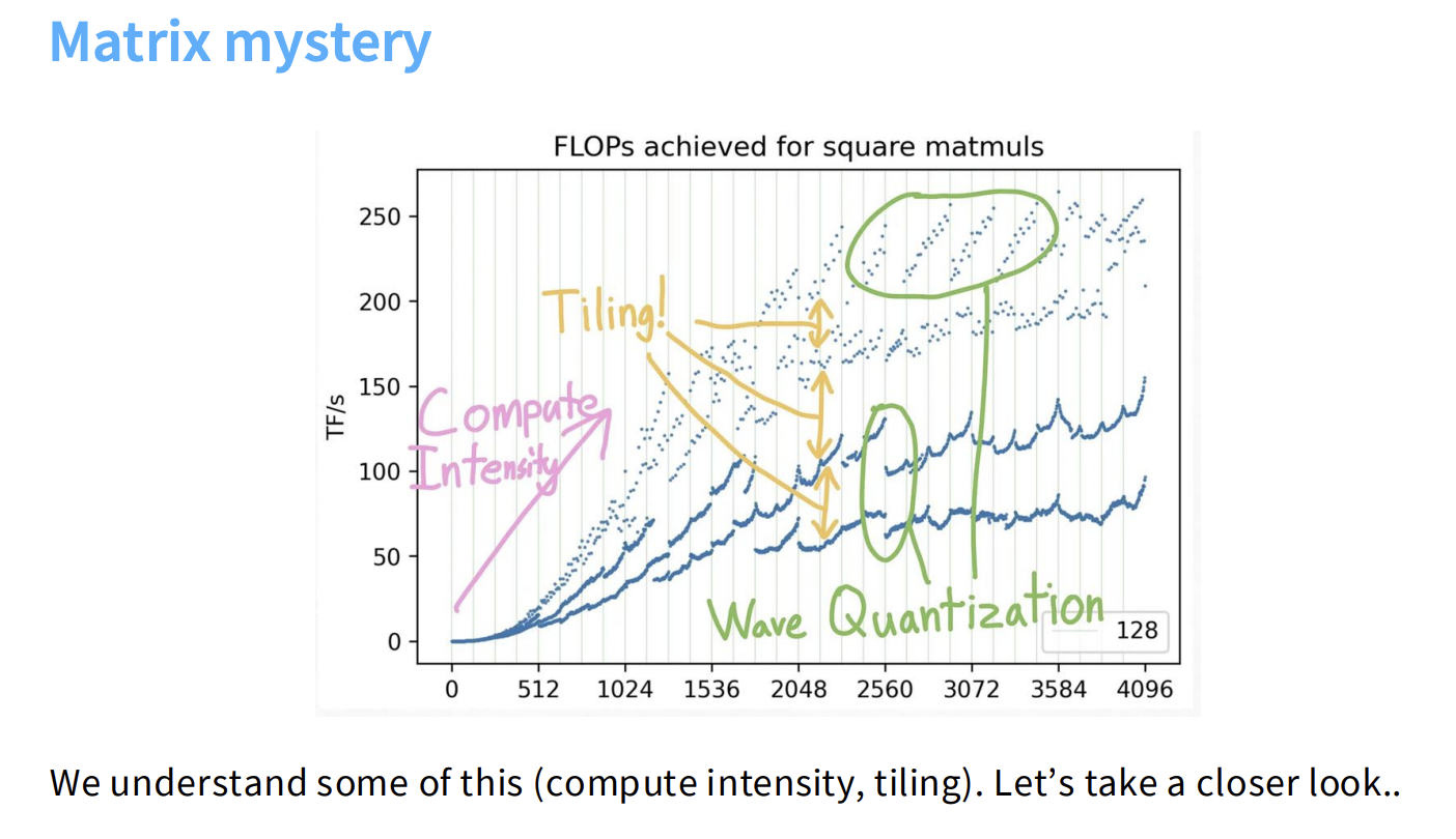 The “unpredictable looking wavelike patterns” in GPU performance for matrix multiplications can be explained by:
- Roofline Model: As matrix size increases, performance improves due to better compute intensity (compute-bound regime).
- Tiling Alignment and Divisibility: Performance drops significantly when matrix dimensions are not divisible by certain numbers (e.g., 32, 16, 8). This prevents efficient tiling and coalesced memory reads.
- Wave Quantization: Sharp drops in performance at specific matrix sizes occur when the number of tiles exceeds the available SMs on the GPU. This forces some SMs to run low-utilization tiles, causing overall performance to plummet.
“An A100 has 108 SMs, so it cannot execute all 120 tiles.”
3. FlashAttention: A Case Study in GPU Optimization
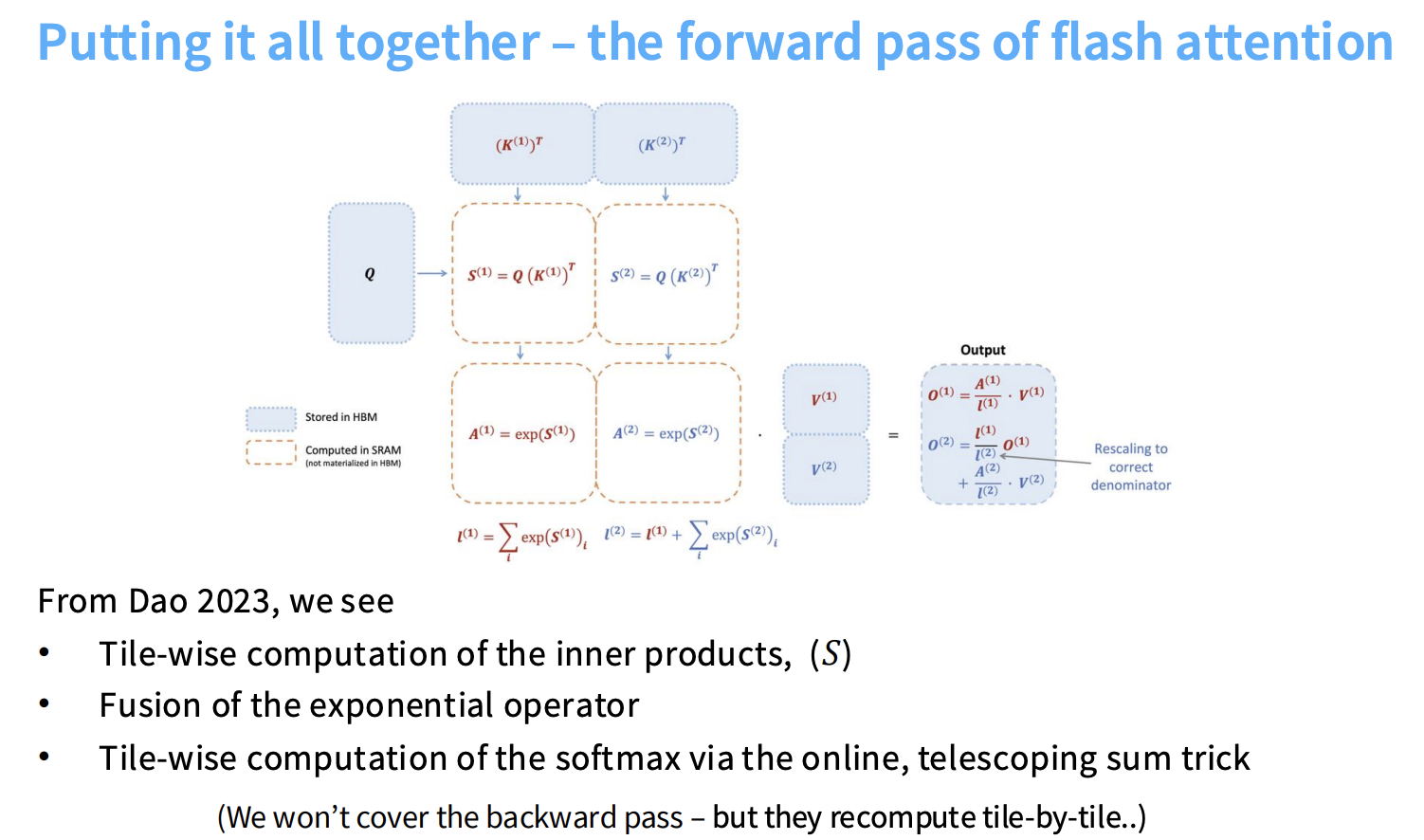
FlashAttention is a prime example of applying these GPU optimization principles to accelerate the transformer’s attention mechanism. It tackles the challenge of “computing exact attention in sub quadratic HBM accesses.”
3.1. Attention Computation Recap
Attention involves three matrix multiplies (Q, K, V) and a softmax operation. The challenge is the softmax, a global operation that is traditionally problematic for tiling.
3.2. FlashAttention’s Core Techniques
-
Tiling for KQV Matrix Multiply: Ensures that the matrix multiplications are performed with minimal global memory access.
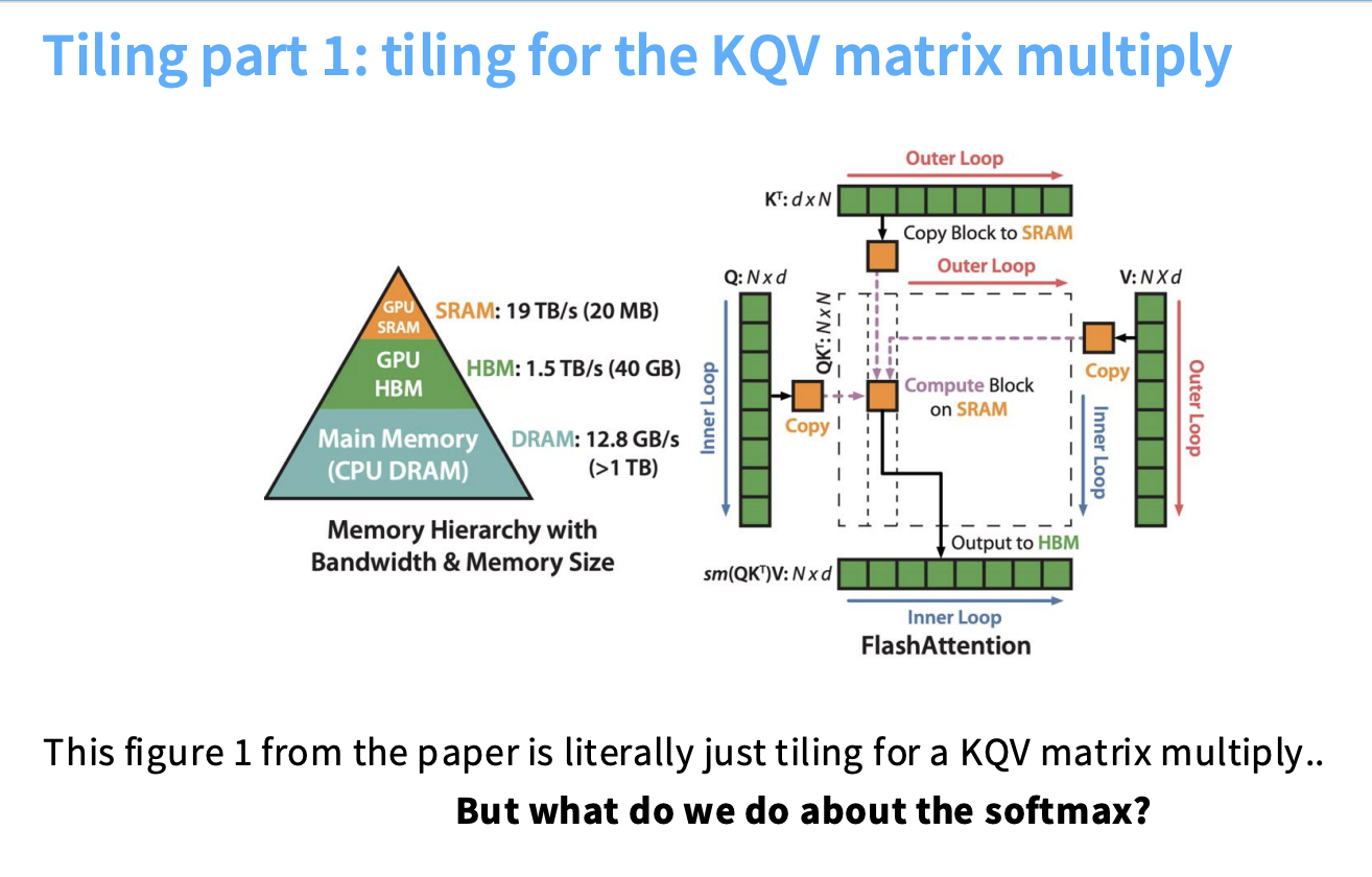
- Incremental (Online) Softmax Computation: Allows the softmax to be computed “tile-by-tile” by incrementally updating the maximum value and a telescoping sum. This avoids “materializ[ing] the full N^2 matrix.”
- Fusion of Exponential Operator: The exponential operation within the softmax is fused with other operations.
- Recomputation for Backward Pass: Uses recomputation “tile by tile” to avoid storing the large N^2 sized softmax activations.
By integrating these techniques, FlashAttention achieves significant speedups by “think[ing] carefully about the GPU (coalescing, tiling, fusion).”
3.3 Online Softmax Example
Normal softmax over a sequence of scores x_1, ..., x_n is:
softmax_i = exp(x_i) / Σ_j exp(x_j)
This is problematic because you need all x_j to compute the denominator, and large x values can cause numerical instability.
Online softmax streams through the data, maintaining:
m_j: maximum of values seen so far.l_j: sum of exponentials adjusted by the current max.
Example — Element-wise for [2.0, 1.0, 5.0]
Step 1: Start with 2.0
m_1 = 2.0l_1 = exp(2.0 - 2.0) = 1.0
Step 2: Add 1.0
m_2 = 2.0(max doesn’t change)l_2 = l_1 + exp(1.0 - 2.0) = 1.0 + 0.3679 = 1.3679
Step 3: Add 5.0 (new max!)
m_3 = 5.0- Rescale old sum:
l_2 * exp(m_2 - m_3) = 1.3679 * exp(-3.0) = 0.0681 - Add new term:
exp(5.0 - 5.0) = 1.0 l_3 = 0.0681 + 1.0 = 1.0681
Final softmax values:
softmax = [0.0466, 0.0171, 0.9363]
Why This Helps in FlashAttention:
- Avoids materializing the whole N×N attention score matrix.
- Processes each tile in fast shared GPU memory.
- Improves GPU compute utilization by keeping data on-chip.